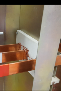
Why “Overvoltage Performance” testing is essential (Dielectric tests)?
Why “Overvoltage Performance” testing is essential (Dielectric tests)?
AS/NZS 61439 requires dielectric testing as part of:
- The design verification process
- The routine verification of production switchboards.
Successfully verifying your switchboard’s dielectric strength is important because it ensures your switchboard’s busbar system will handle normal and overvoltage conditions. Overvoltages may occur due to lightning strikes, HV switching (transient overvoltages), or a large network load switching off (temporary overvoltages). Transient and temporary overvoltages can compromise the safety of your switchboard, however, are generally protected by surge protective devices (AS/NZS 1768) and phase failure relays with overvoltage protection (AS3000).
 |
 |
But there are also other reasons to verify your switchboard’s dielectric performance. The following are some common causes of failure at normal operating voltage:
| CAUSE OF FAILURE | FURTHER DISCUSSION |
| Faulty Equipment | Although very rare, switchgear can be faulty out of the box. Dielectric testing after switchboard construction will pick this up. |
| Manufacturing error | A dielectric test will determine if the switchboard builder has unintentionally not allowed enough clearance or creepage distance between phases and phase-to-earth.
Generally, switchboard builders use AS/NZS 61439.1 Table 1 & 2 as a guide with a safety margin between their busbar supports, and if these distances can’t be attained, will use insulation to achieve compliance. |
| After a short circuit fault | A short circuit fault can cause:
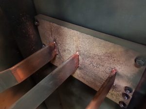
1. Pitting of busbars resulting in a copper spray within the switchboard. 2. Busbars can warp reducing the clearance distances. 3. Protective device operation to clear a fault, can eject carbon that has highly conductive properties. 4. Protective device is damaged during the fault. After a short circuit fault, it is recommended that a Dielectric test is conducted on your switchboard to ensure clearance and creepage distances have not been compromised and that the equipment itself is still fit for use. |
It is also essential for operators to regularly inspect and clean their switchboards as part of their preventive maintenance regimes to ensure there is no dust build up over time that may compromise the creepage distances.
JPR’s switchboard technicians can assist you with your regular and breakdown switchboard maintenance needs. Find out more here…
Here are some more helpful points for designers!
| CLEARANCE AND CREEPAGE DISTANCES, DIELECTRIC PROPERTIES
TABLE D.1 CHARACTERISTICS 3, 4 & 9 Refer: Informative Appendix F for some good explanatory diagrams of clearance and creepage distances |
||
| Characteristic | Definition | Helpful points for designers |
| Clearance | Distance through the air between phases, and phase-to-earth | Verified by Impulse withstand test voltage (10.9.2)
If a main switchboard, minimum 6kV test impulse voltage If a distribution board, minimum 4kV test impulse voltage
(Note: The NATA test station can perform an alternative test using a hi-pot to the same voltage level above as per 10.9.3)
Measurement by hand between phases and earth using Table 1
|
| Creepage distance | Distance measured along the surface between phases, and phase-to-earth | Verified by Power frequency withstand test voltage (hi-pot):
690V insulation – test at 1890kVac 1000V insulation level – test at 2200kVac
Measurement by hand between phases and earth using Table 2, but you need to know the material group (Comparative tracking index) of the busbar insulator and the pollution degree of the switchboard location |
| Note 1: Remember overvoltage and surge protection devices give you added protection and must be removed when performing dielectric tests above!
Note 2: Modern circuit breakers can have electronic protection equipment in them that generally needs to be disconnected before the dielectric test is performed. Always consult the manual before testing! |
||

